Using a Aldi Workzone WIFI smart socket without Tuya-cloud (OpenBK7231T installation tutorial)
Recently, Aldi had some WIFI plugs on offer. They cost 12,99€ each and are originally working with the Tuya cloud.

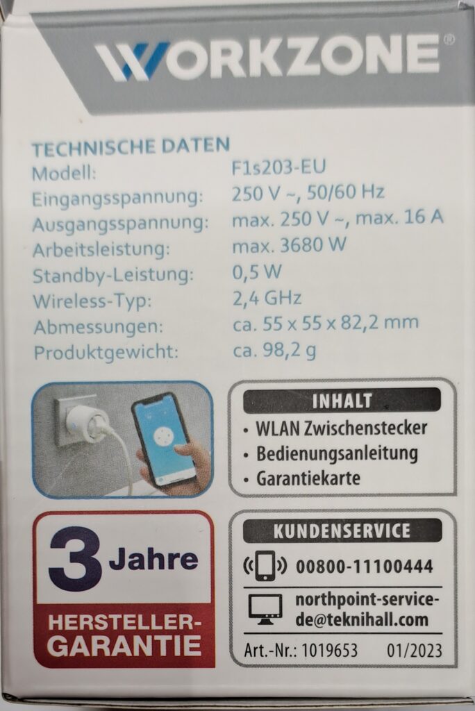

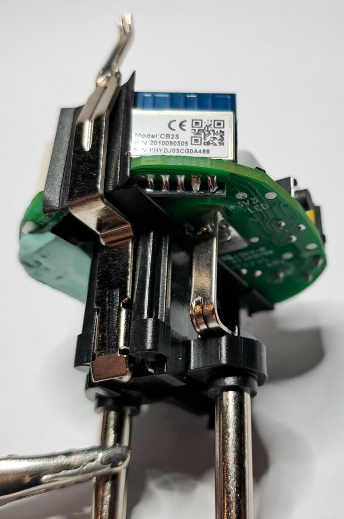
Unfortunately those sockets are not based on the common ESP8266 chip an thus cannot be easily flashed over the air with Tasmota. They are using a chip called CB2S, wich is special 32-bit MCU developed by Tuya. However, there is another open source software called OpenBK7231T/OpenBeken, which is working simmilar to Tasmota and can work on these sockets.
Sadly there is no opportunity to remove the stock firmware without opening the device (OTA-flashing is not supported (yet)).
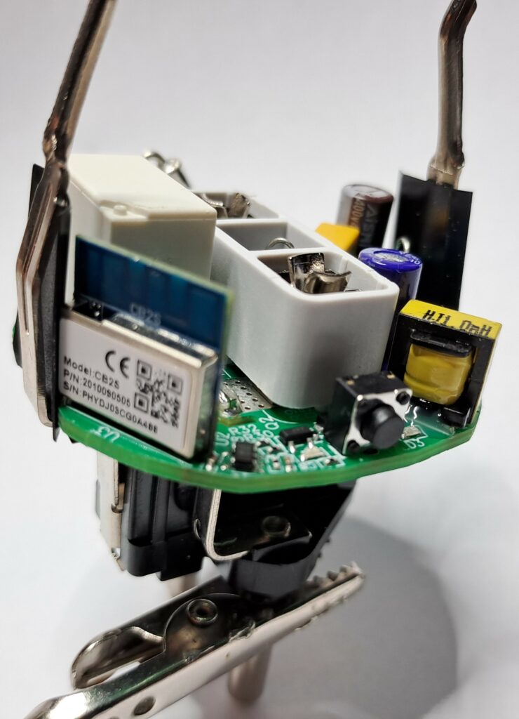
Opening and reverse engineering
WARNING: This post is just a „proof of concept“. Every modification of the socket happens at your own risk. Inside the case there can be lethal voltages, even if the socket is not plugged in. The manufacturer’s warranty will most likely expire if the device is opened or the firmware is modified.
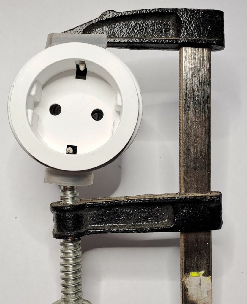
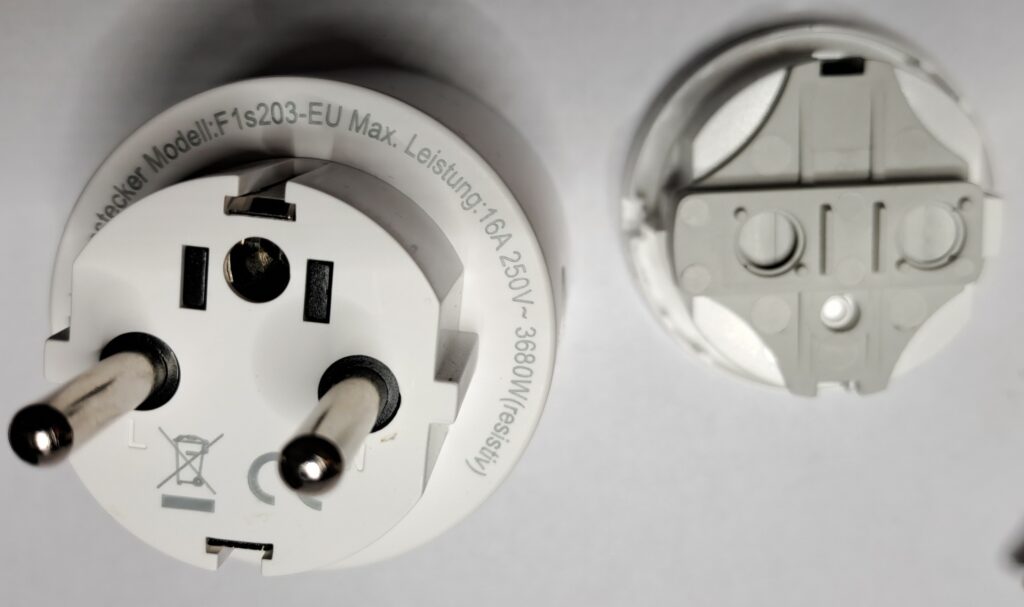
To open the device, use a screw clamp to squeeze the enclosure of the plug until you have enough space to push a screwdriver into the gap at the output socket and remove the top cover.


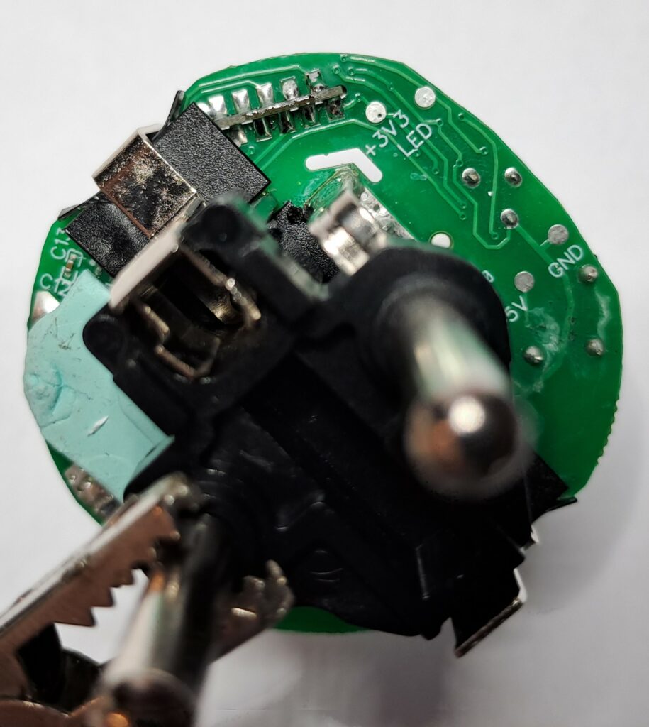
PCB
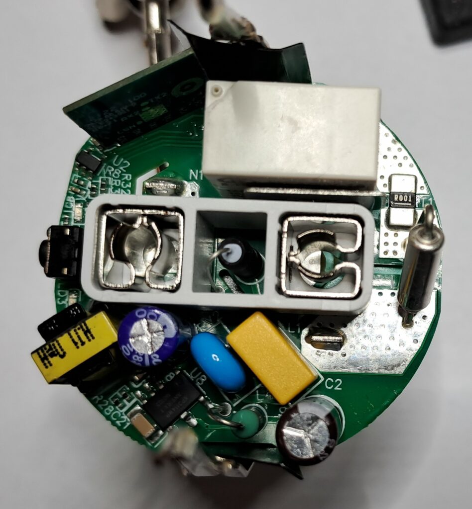
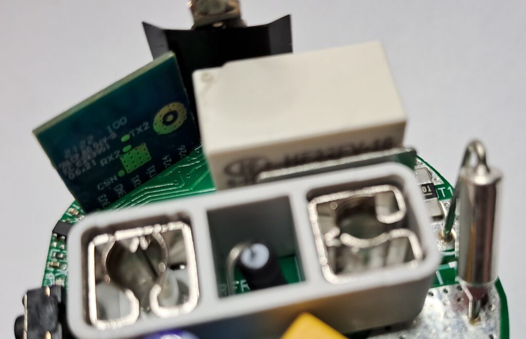
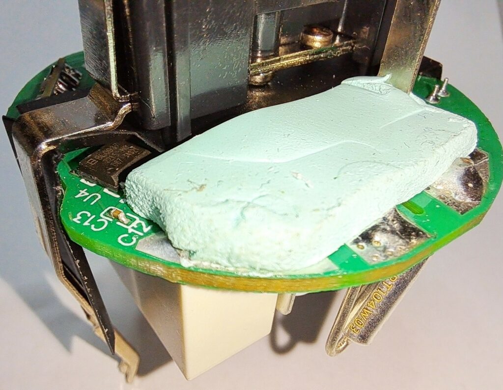

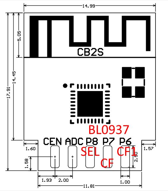
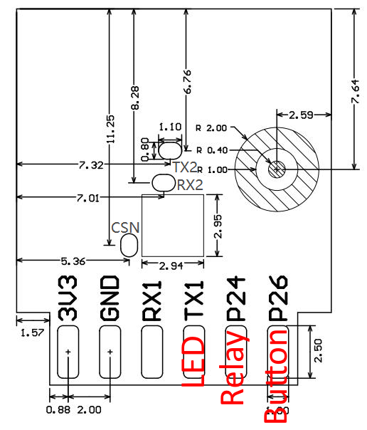
Pinout of the CB2S chip
The chip is using a BL0937-chip for current/consumption measurement.
Flashing the OpenBK firmware
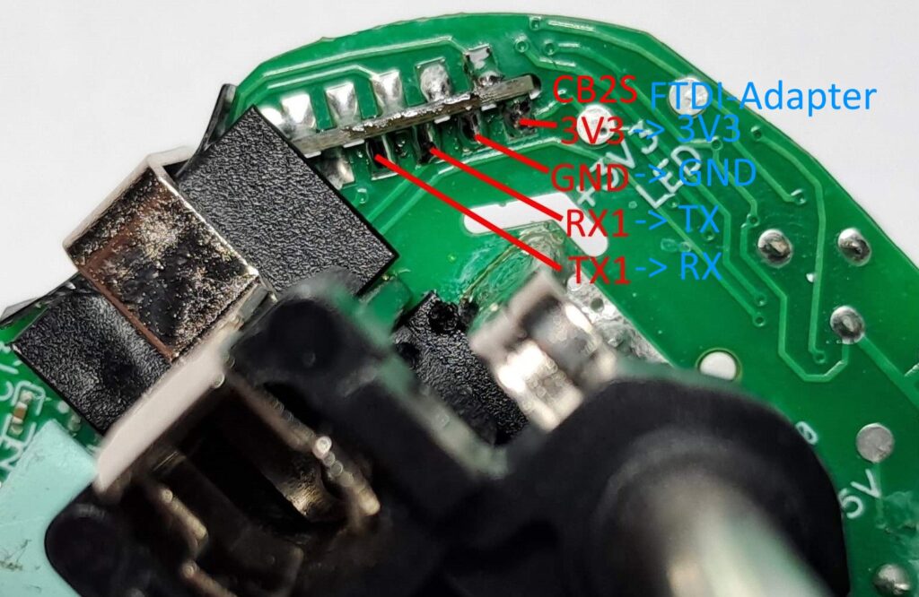
For flashing the chip connect a FTDI-USB-adapter to the 3V3, GND, RX1 and TX1 lines of the module (make sure the socket is NOT plugged in!!!, the chip is powerd through the FTDI-adapter).
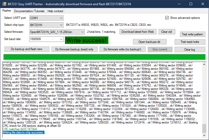
You can use the BK7231 GUI Flash Tool (https://github.com/openshwprojects/BK7231GUIFlashTool) to upload the OpenBK7231T-firmware. Select the corresponding COM-port of the FTDI-adapter. chip type: BK7231N, baud rate: 1500000. Press „Do firmware write (no backup!)“ and AFTER that connect the 3V3 line to the FTDI-adapter („Do backup and flash new“ should better be used but this did not work in my case). After a short time you should see the message „Write success!“.
Configuration of the OpenBK7231T-firmware
After flashing the firmware and reconnecting the power, the chip is creating a Wifi Access Point (no password required). Connect to this Wifi and visit the Website 192.168.4.1. The interface looks simmilar to Tasmota. Go to „Config“ and „Configure Module“ and make the following entries:
- P6 (PWM0) -> BL0937CF1
- P7 (PWM1) -> BL0937CF
- P8 (PWM2) -> BL0937SEL
- P11 (TXD1) -> WifiLED (or another LED functionality as you wish)
- P24 (PWM4) -> Rel 0
- P26 (PWM5) -> Btn 0 0
To use the power monitoring feature you need to activate the sensor first. Open „Config->Execute custom command“ and enter
startDriver BL0937Now you need to calibrate the sensor. Connect an (resisive) load with a known consumption (for example a incandescent light bulb) to the socket. You can double check the values with a energy meter. Now activate the output of the socket (relay on) and enter the values of your load using those commands (replace the example values with your measurements):
VoltageSet 232.0
CurrentSet 0.475
PowerSet 110.0
After that the calibration is done.
Now you can configure the Wifi- and a MQTT-connection.
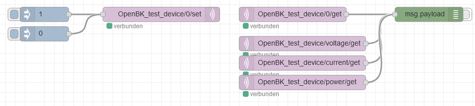
example for simple control and power monitoring using Node Red
The exact MQTT-command list can be found on the Github page of the QpenBK-project. It is not fully compatible to the Tasmota MQTT command set.
useful links
- Aldi listing: https://www.aldi-nord.de/angebote/aktion-do-05-01/smarter-wlan-zwischenstecker-1019653-0-0.article.html
- OpenBK7231T-project: https://github.com/openshwprojects/OpenBK7231T_App
- CB2S Module Datasheet: https://developer.tuya.com/en/docs/iot/cb2s-module-datasheet?id=Kafgfsa2aaypq
- OpenBK7231T flashing tool (Windows): https://github.com/openshwprojects/BK7231GUIFlashTool
2 Kommentare
poiuzzz · 22. Mai 2024 um 20:14
Thanks for the good instructions.
I tried, but although my board looked exactly the same, the settings are not right. I found the right ones here: https://www.elektroda.com/rtvforum/topic4040624.html
Maybe it will help one or the other maker 🙂
brun · 25. Mai 2024 um 10:10
Thanks for this information. Maybe they changed the layout in a new version of the socket …